| 100
| png ps
| png
| JPG
(src)
, JPG
| 106
| png ps
| png
| JPG, PNG
|
|---|
| 122 | (2020 model)
|
|---|
| cf188
| png ps
| png
| JPG 1, 2
|
|---|
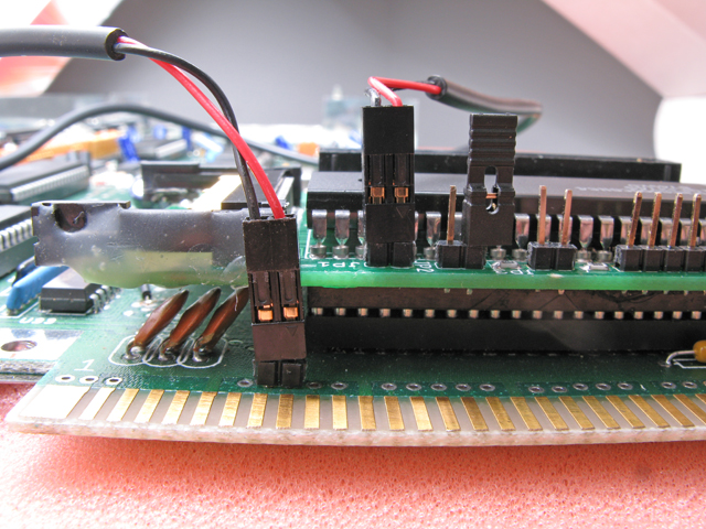
| cf208
| png
| png
| A2K JPG1, 2
|
|---|
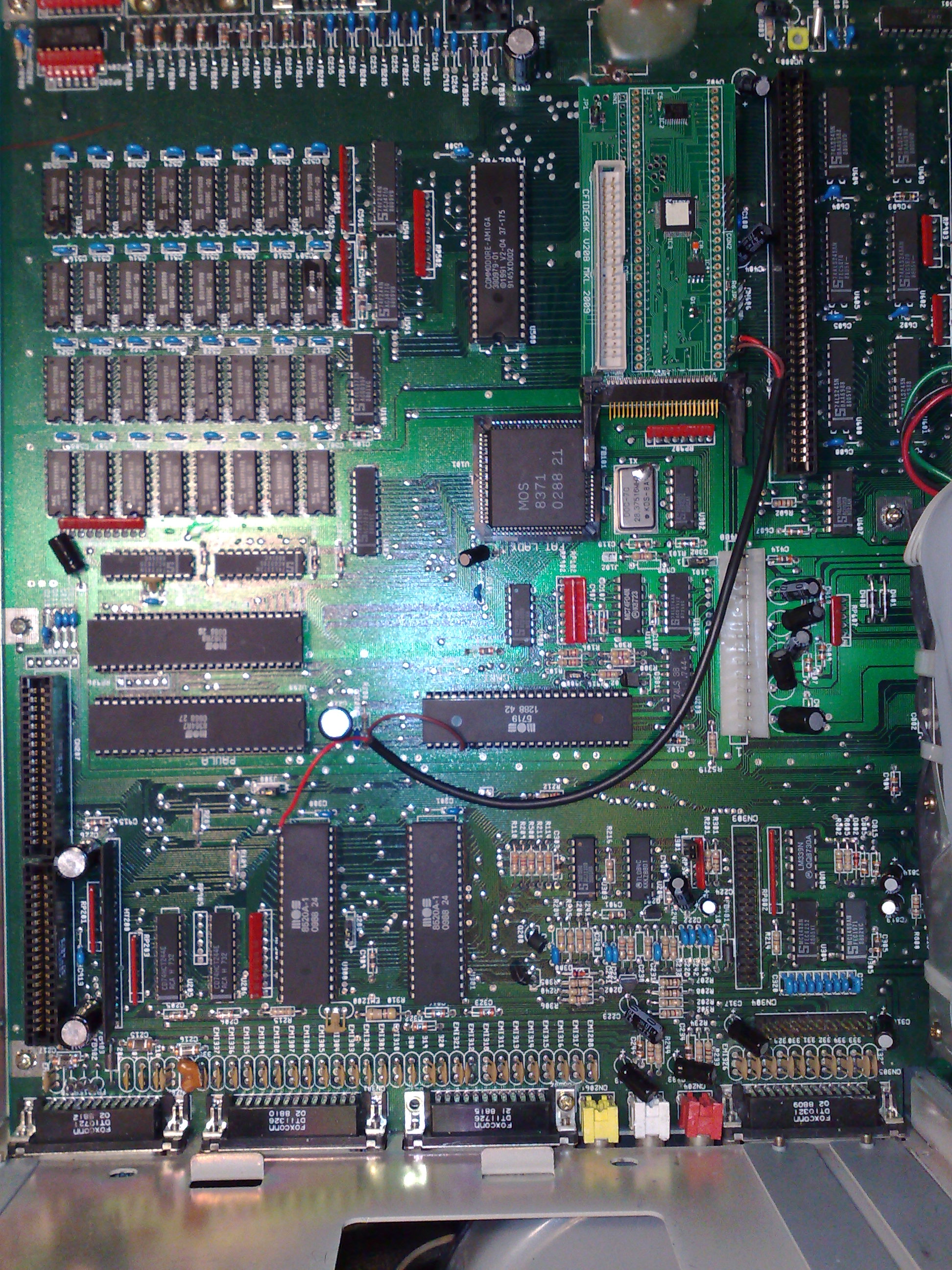
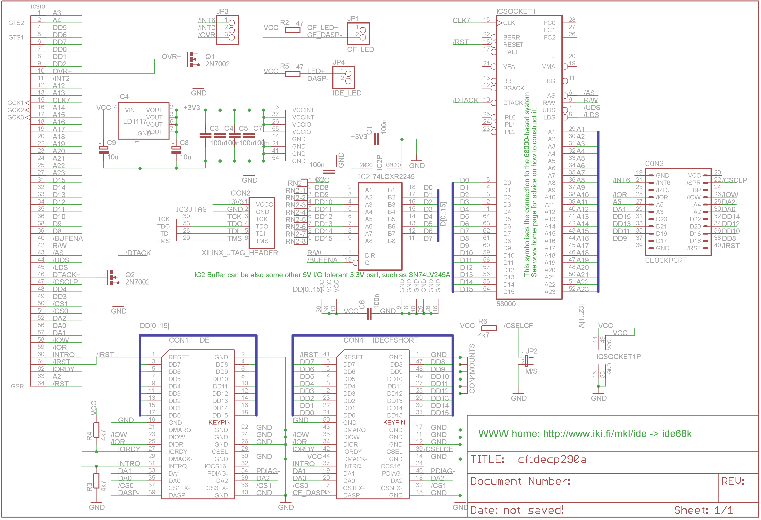
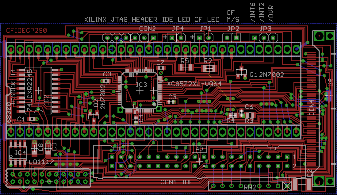
| cfcp290
| png
| png
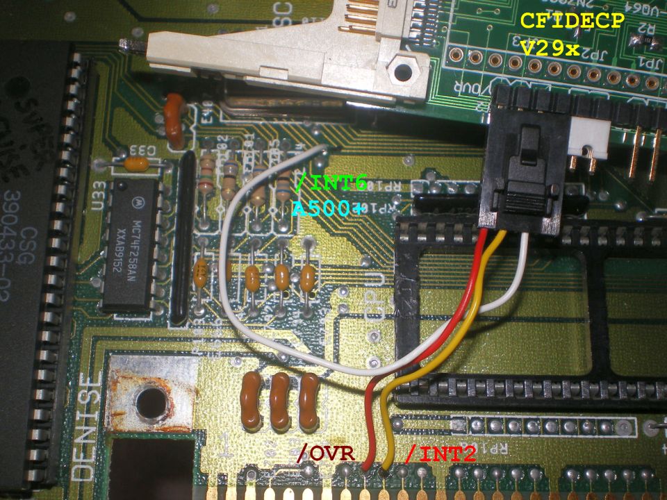
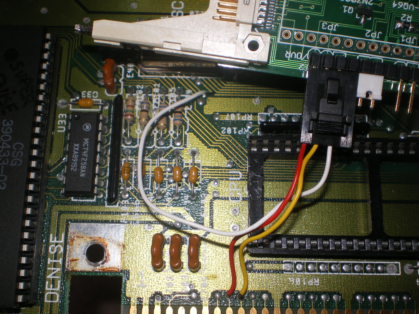
|
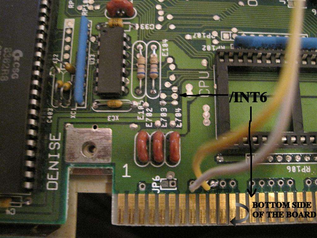
V6a-A500
JPG
A500+ JPG, BIG
|
|---|
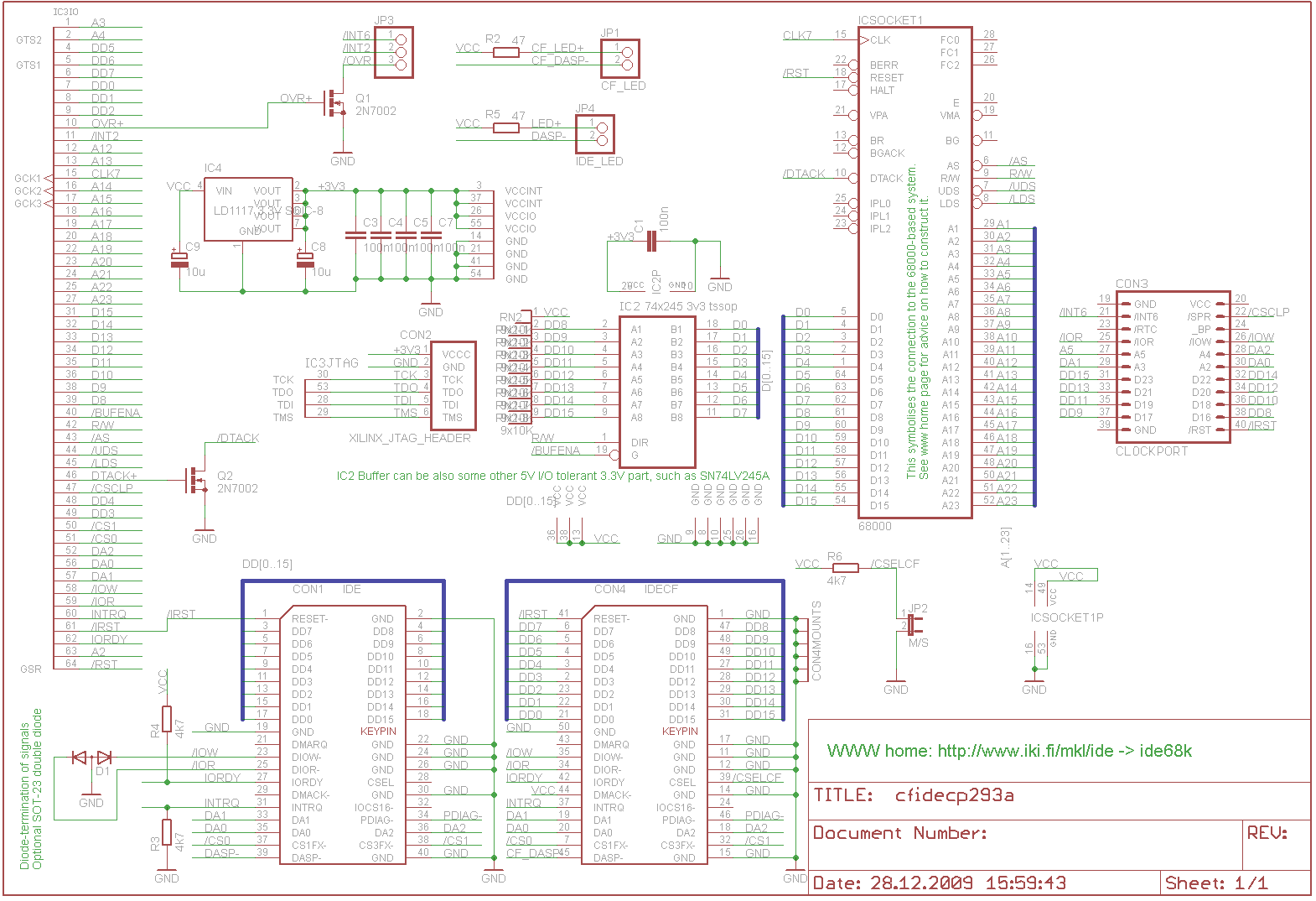
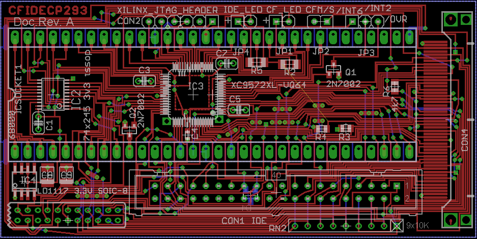
| cfcp293
| png
| png
|
|---|
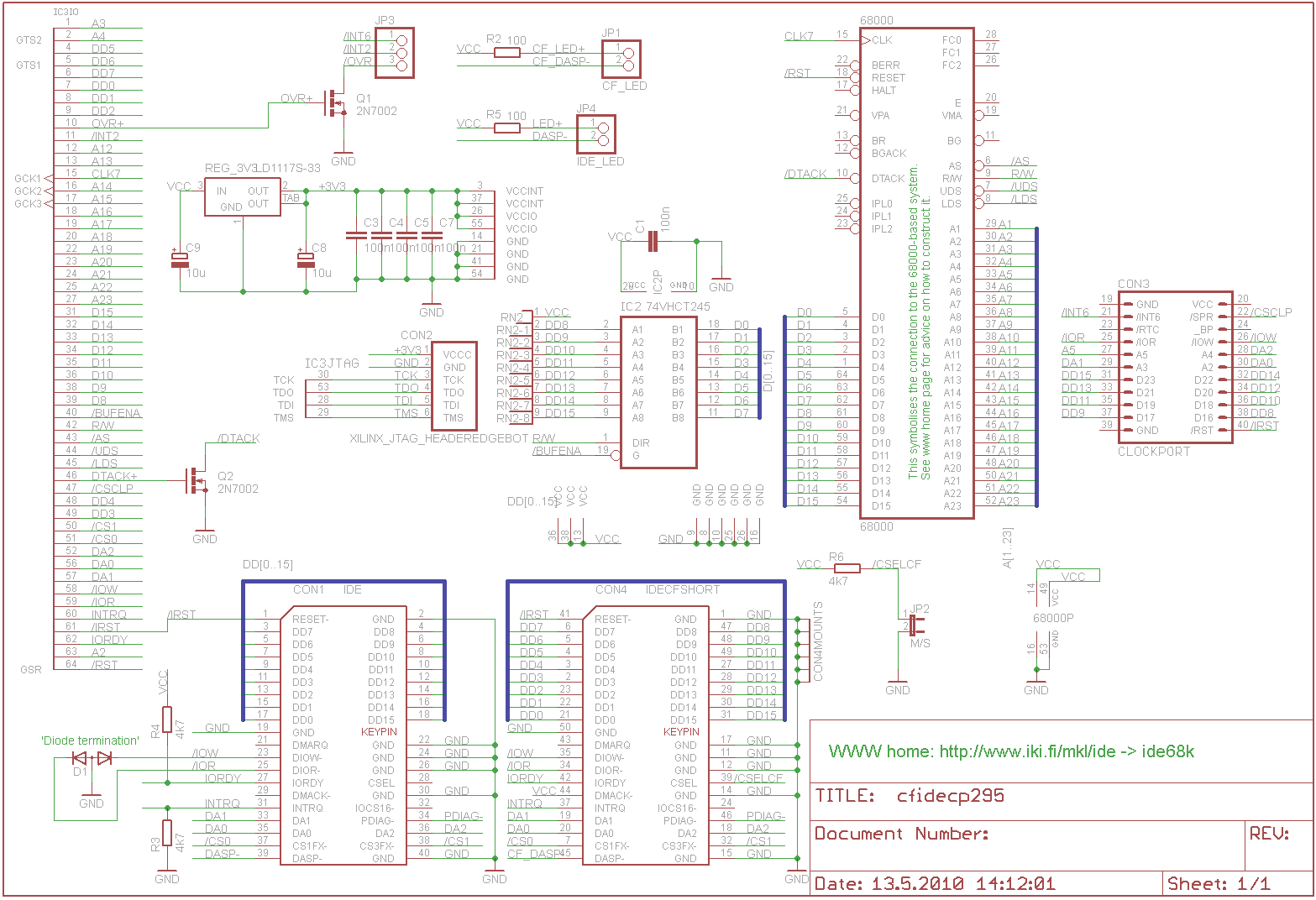
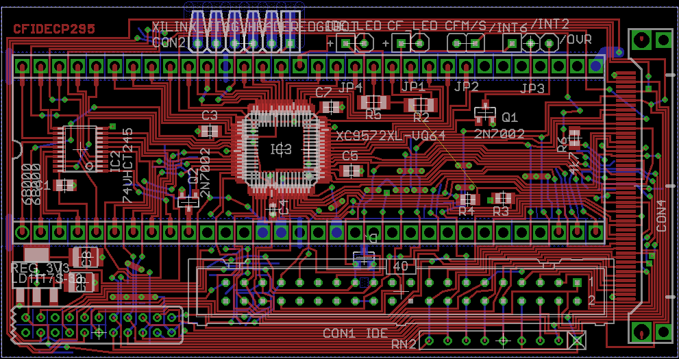
| cfcp295
| png
| png
|
|---|
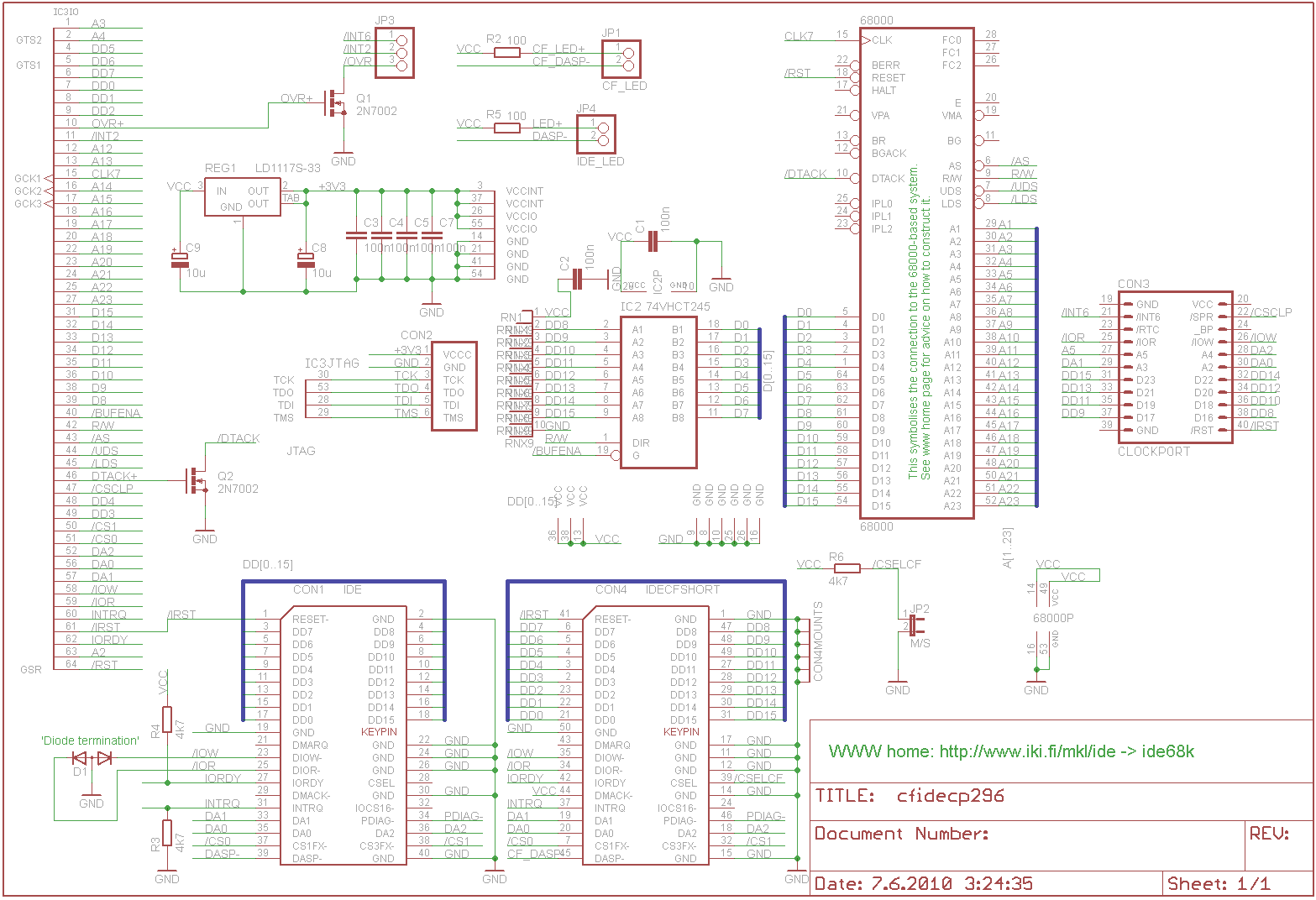
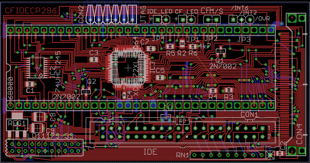
| cfcp296
| png
| png
|
|---|
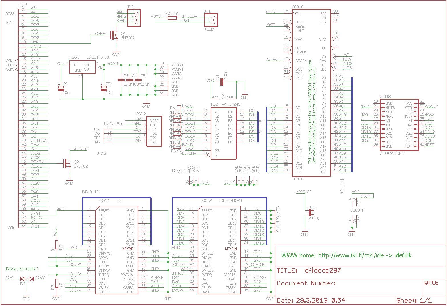
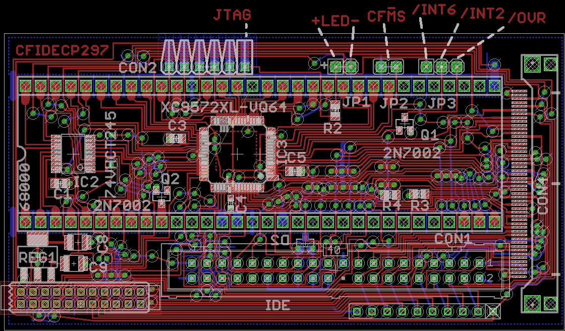
| cfcp297
| png
| png
|
|---|
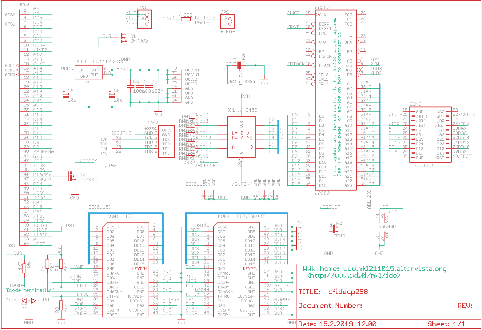
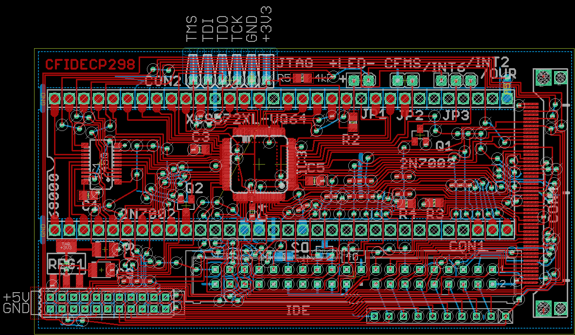
| cfcp298
| png
| png
|
|---|
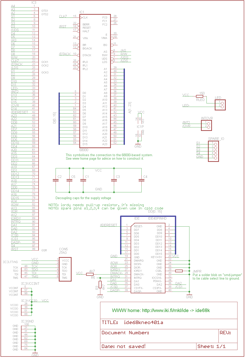
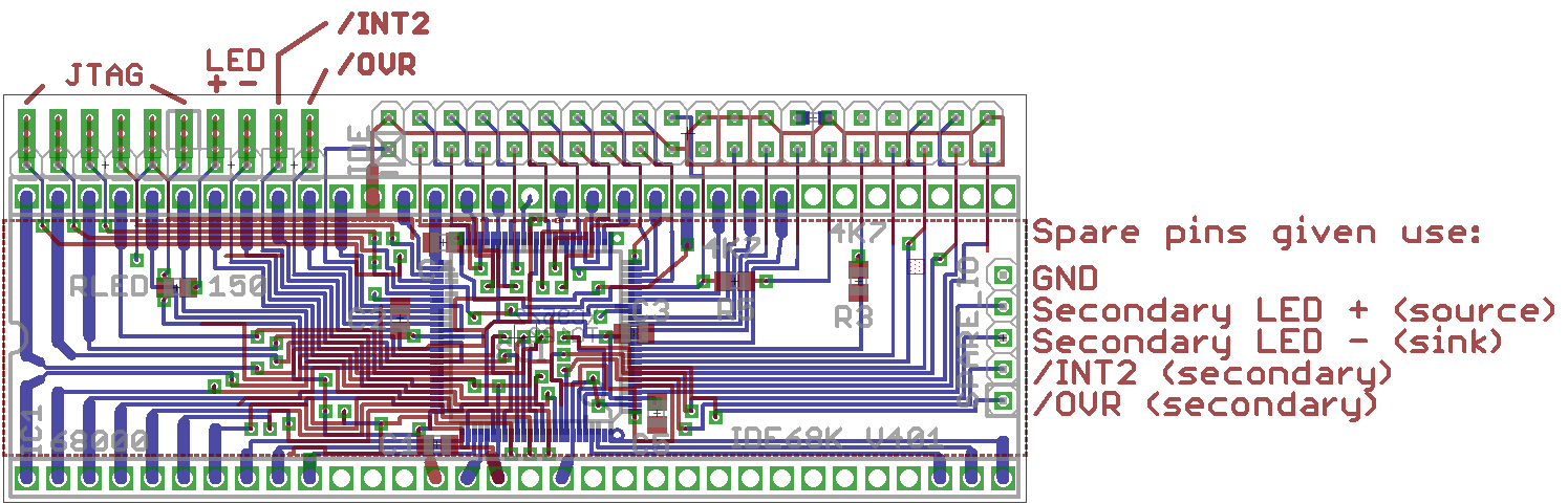
| 401
| png
| png
|
|---|
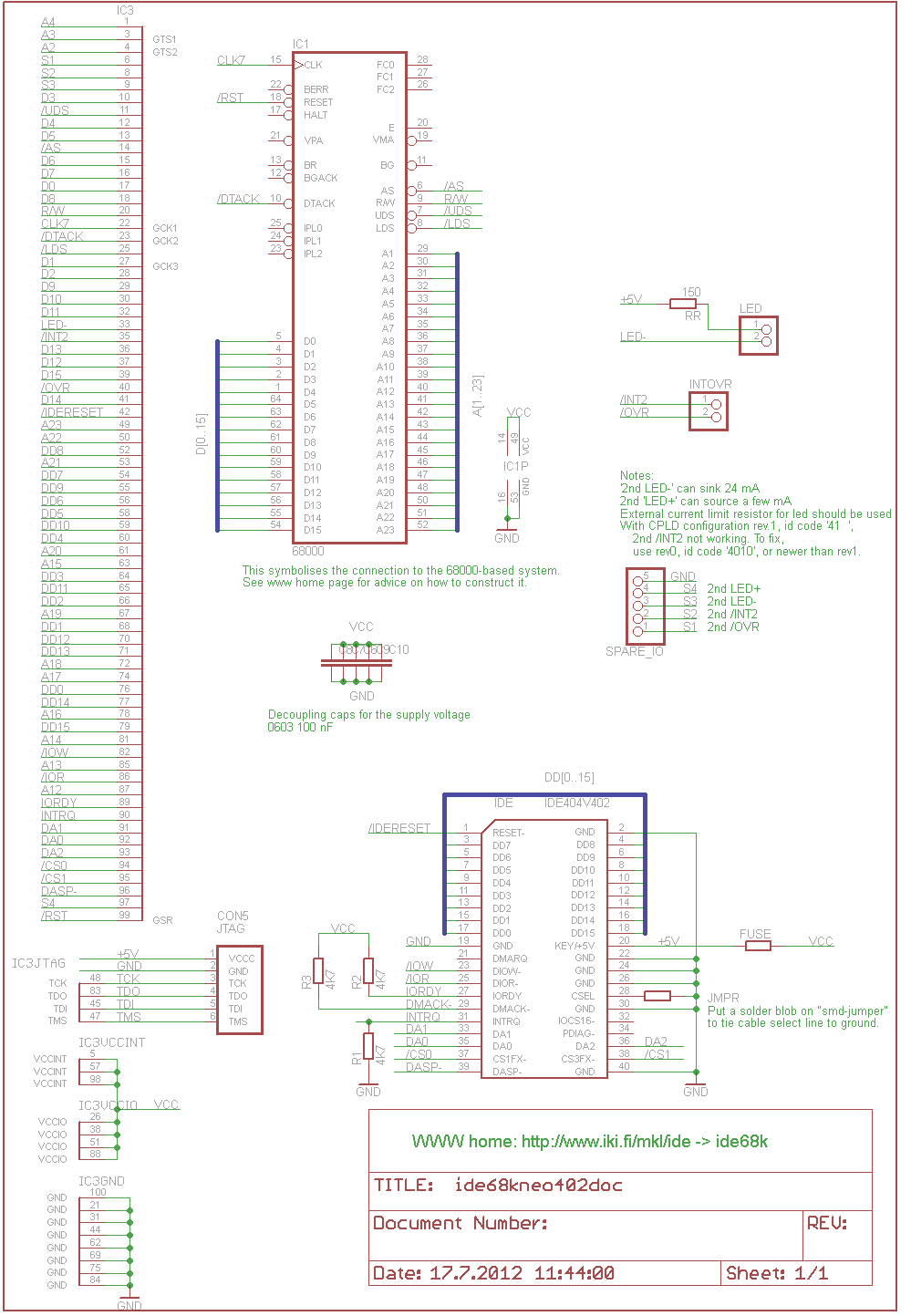
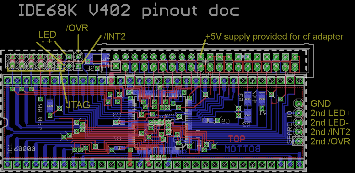
| 402
| png
| png
|
|---|
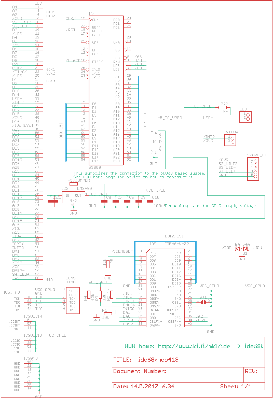
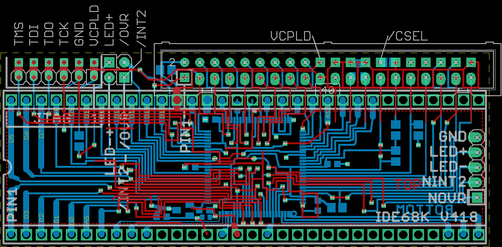
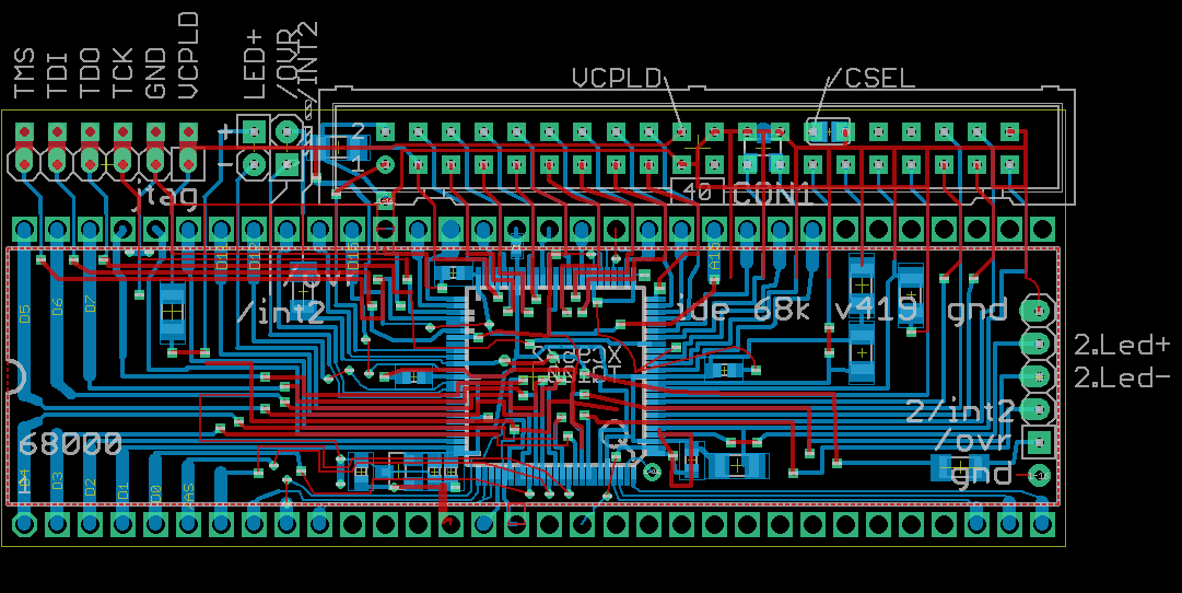
| 418
| png
| png
|
|---|
| 419
| png
| png
|
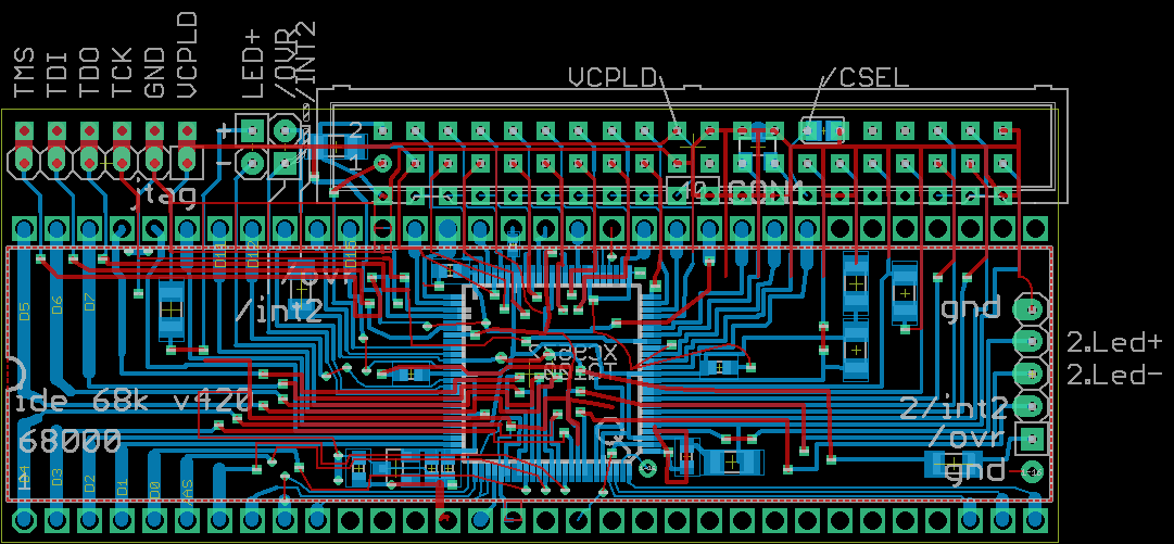
|---|
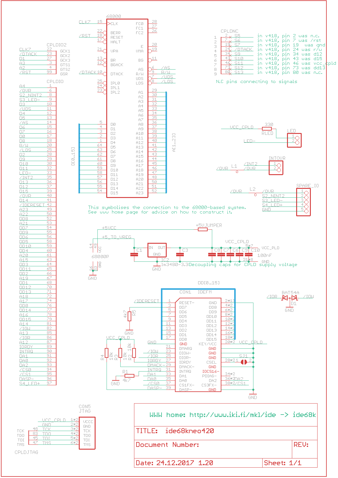
| 420
| png
| png
|
|---|
| 421
| png
| png
|
|---|
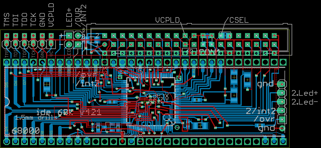
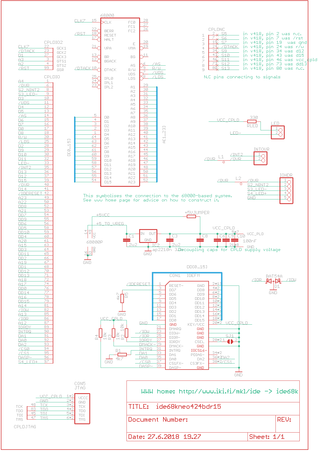
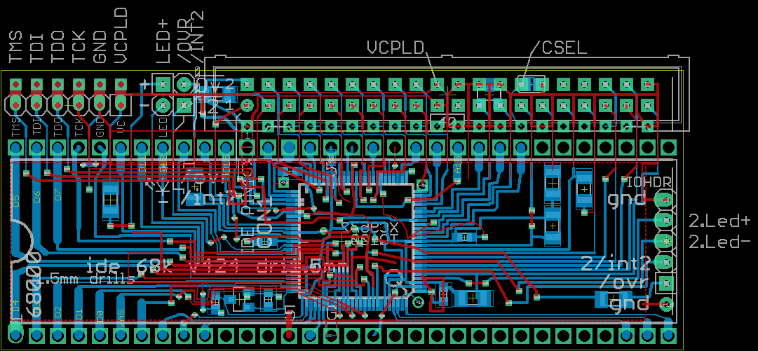
| 424
| png
| png
|
|---|
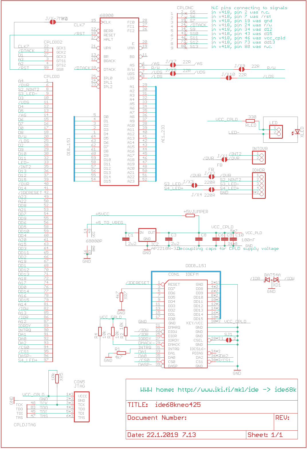
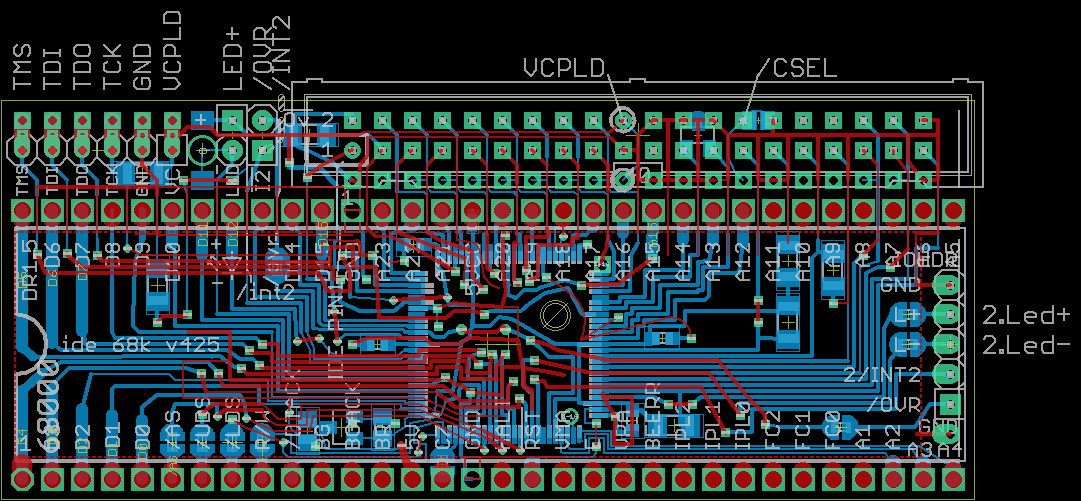
| 425
| png
| png
|
|---|
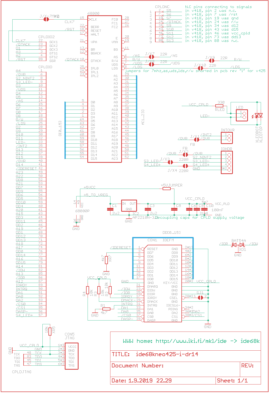
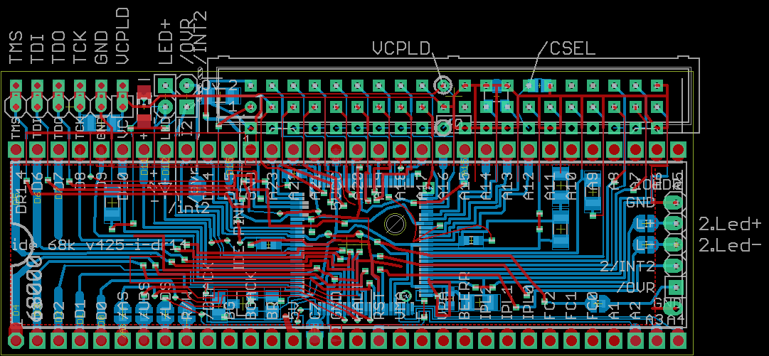
| 425i
| png
| png
| gerbers, for personal use, not licensed for mass production
|
|---|
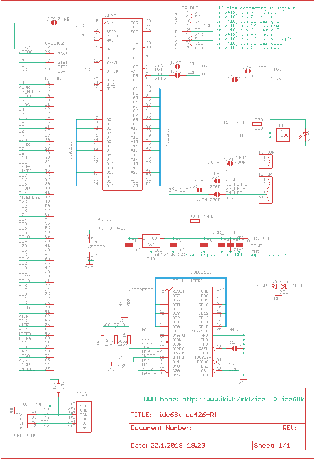
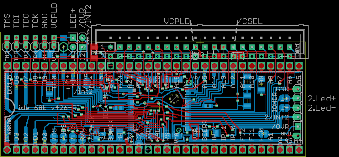
| 426-RI
| png
| png
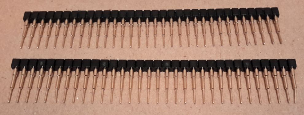
| Female 40 pin right angle socket header on bottom side of board
|
|---|
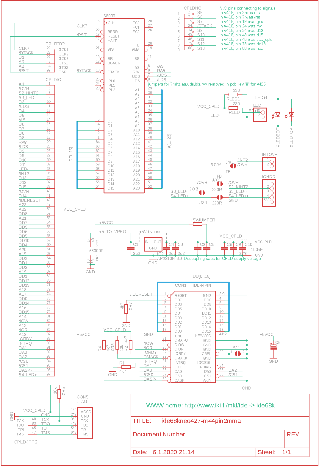
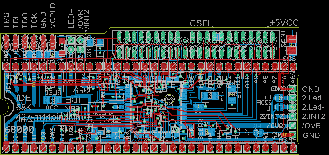
| 427m44
| png
| png
| male 44 pin (2.0mm) header (on top)
|
|---|
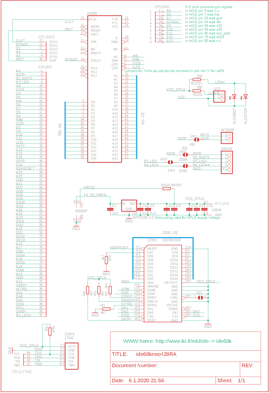
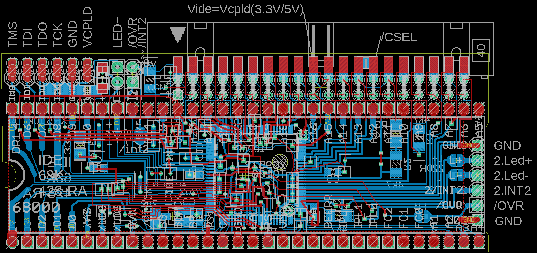
| 428ra
| png
| png
| right angle 40 pin header - or 40 pin header soldered to card's edge (therefore right-angle)
|
|---|
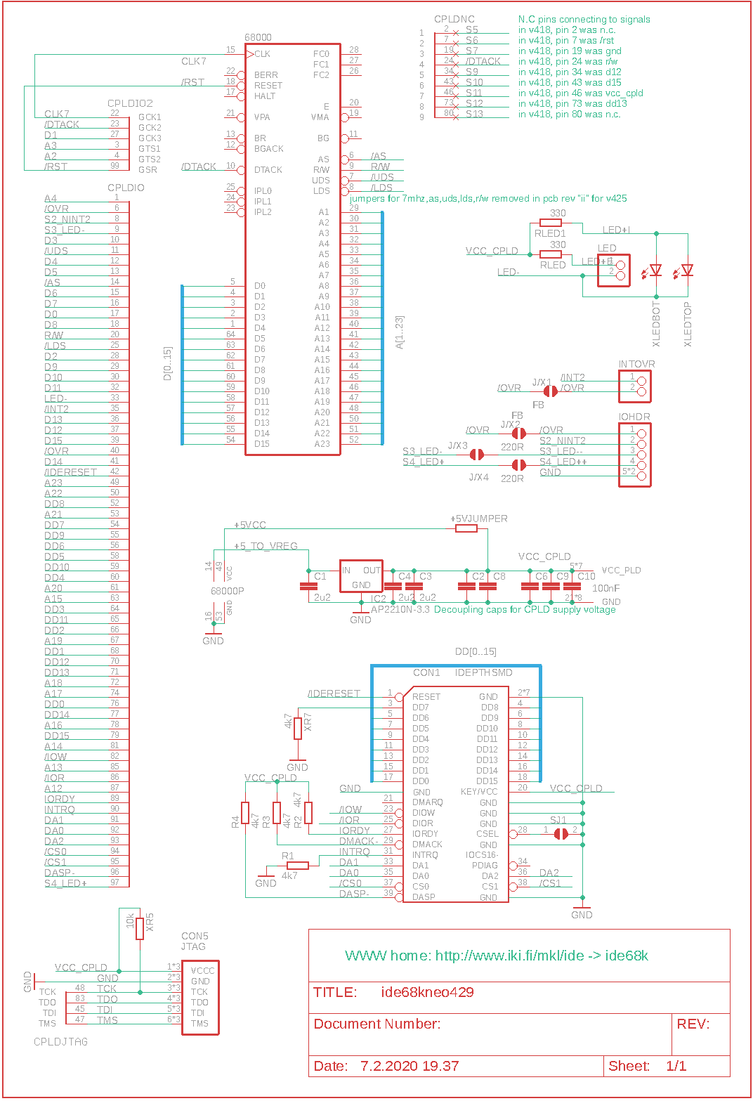
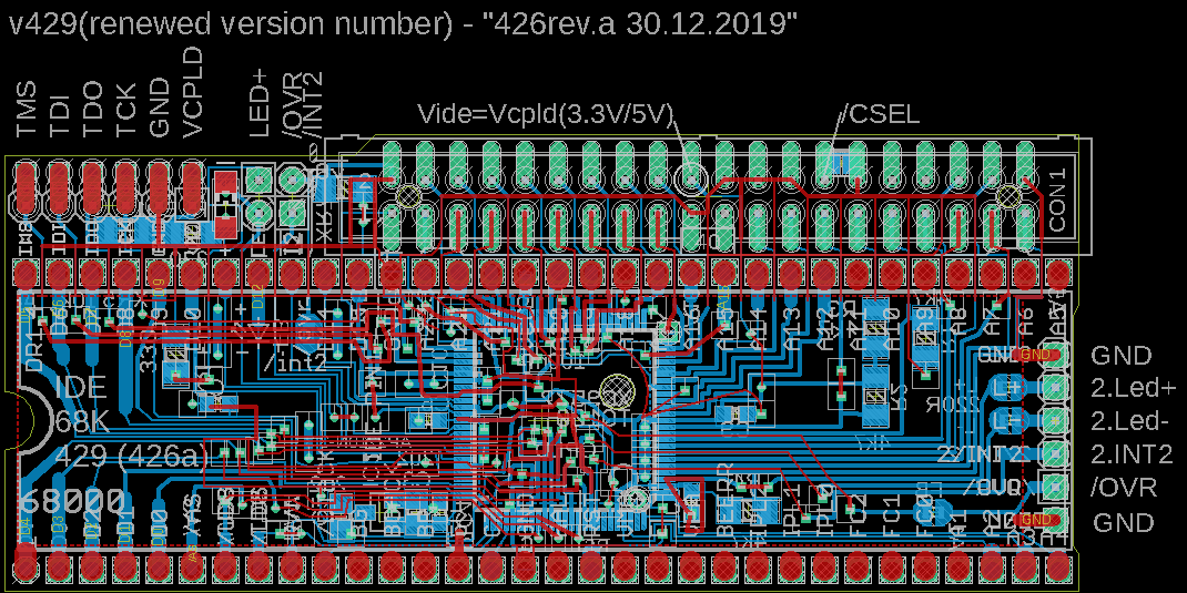
| 429
| png
| png
| wide pads for 40 pin header - (proto pcb text "426a")
|
|---|
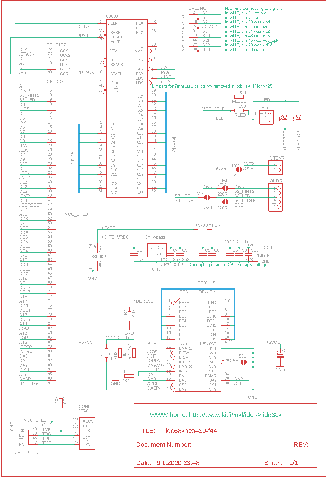
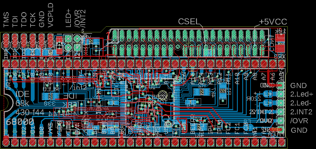
| 430f44
| png
| png
| female 44 pin (2.0mm) socket (on top)
|
|---|
|
|---|